|
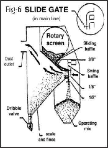
Fig - 6
|
|
The drop of air pressure on separator can be too great, causing the removal of good shot with sand.This can be corrected by adjusting the blast gate sliding baffle and swing baffle. If the separator is functioning properly, sand will continue to come out of dribble valve when shot blasting machine is running. As the effective operation of the separator depends on the airflow, please ensure that filter collector either bag type or ultra-jet or cartridge type is operating efficiently.
|
|
|
|
| MAGNETIC SEPARATOR :(Fig.7) |
|
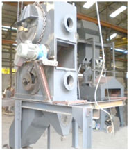
Fig - 7
|
|
Patel Furnace offers magnetic separator Fig-7 when there is extremely heavy sand load condition. For example large size steel valve body has very heavy cores. During first three four minutes of blasting sand and shots are released in large quantity. The magnetic separator significantly increases the ability to remove sand from steel shot or grit. The addition of magnetic separator to shot blasting machine increases the life of wearable parts like blade, impeller, control cage, liners etc., because sand is the primary cause of wear.
|
|
|
| Magnetic separator reduces blast cycle time, increases the life of replacement parts, reduces equipment maintenance and abrasive consumption and total operation cost. |
|
|
| Blast Pattern : (Fig. 8,9) |
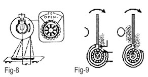 |
| Fig – 8-9 |
|
| Fig 8, Shows Blast Pattern located 8” inches to the right of the Vertical centerline on a clock-wise wheel, The Pattern is called hot Spot and will feel warm to the hand if touched immediately after shot blasting. The ½” movement of control cage opening will shift the Blast Pattern by several inches. Wear tolerance has been built into blast equipment but when wear goes beyond the tolerance components like Blade, Control Cage, Impeller, can not perform properly and blast pattern shifts from set target. When wear on the leading edge of the impeller exceeds 4 to 5mm. The abrasive will hit the back of the blade than being delivered to the throwing face. Fig 9, as a result the hot spot and over all blast pattern becomes badly differed and causes increase blasting time and wear on bare wheel and other wheel components. |
|
| WHEEL UNIT LINERS : (Fig.10,11) |
| The blast wheel is usually enclosed within a housing serving as a safety guard. Abrasive seal around rapidly rotating wheel helps to minimize wear on the housing A series of special alloy cast liners, installed inside the housing. |
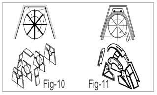 |
| Fig – 10-11 |
|
| Older wheel Fig-10 consisted of 21 liners where abrasive bounces in uncontrolled manner. In our new RLM Fig-11) wheel only nineliners are installed inside the housing. High chrome liners are approx. 25mm thick with labyrinth type joints providing an abrasive tight seal between the liners and give long life. |
|


 New Development in Shot Blasting Process & Maintenance of Equipment (3/4)